
herunterladen
2010 Microchip Technology Inc. DS01355A-page 1
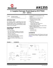
AN1355
INTRODUCTION
An increasing number of applications that involve
time measurement are requiring a Real-Time Clock/
Calendar (RTCC) device. The MCP79410 is a fea-
ture-rich RTCC that incorporates EEPROM, SRAM,
unique ID and time-stamp.
FEATURES OF THE RTCC
STRUCTURE
•I
2
C™ Bus Interface
• RTCC with Time/Date Registers: Year, Month,
Date, Day of Week, Hours, Minutes, Seconds
• Support for Leap Year
• Low-power CMOS Technology
• Input for External Battery Backup (maintains
SRAM, RTCC and Timekeeping)
• On-board 32,768 kHz Crystal Oscillator for the
RTCC
• On-chip Digital Trimming/Calibration of the
Oscillator
• Operates down to 1.3V VBAT Minimum
• Operating Temperature Range:
- Industrial (I): -40C to +85C
• Multi-function Pin:
- Open-drain configuration
- Programmable clock frequency out
- Programmable alarm output
• Interrupt Capability (based on the 2 sets of Alarm
Registers, ALM0 and ALM1)
• Time-stamp Registers for holding the Time/Date
of Crossing:
-from V
DD to VBAT
-from VBAT to VDD
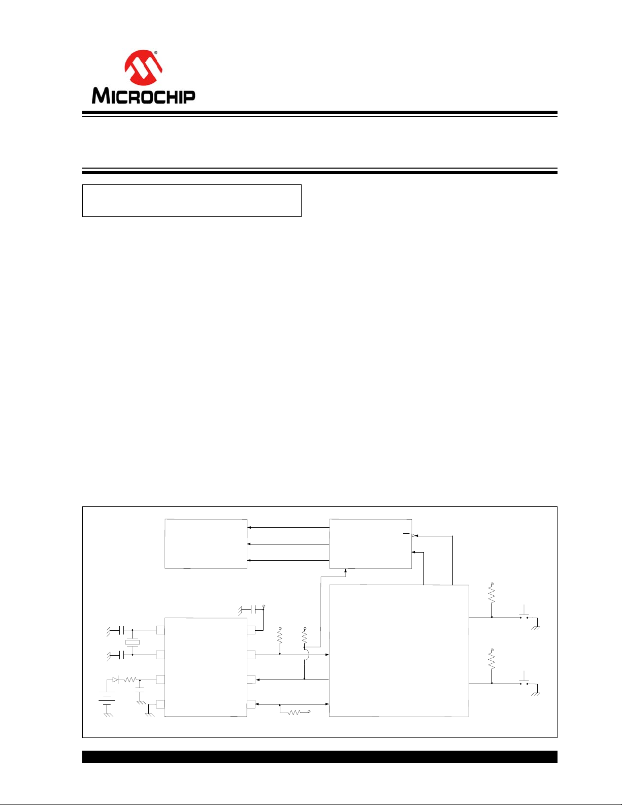
SCHEMATIC
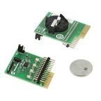
The schematic includes a PIC18 Explorer demo board
and the I
2
C RTCC PICtail™ daughter board as shown
in Figure 1.
FIGURE 1: SCHEMATIC
Author: Alexandru Valeanu
Microchip Technology Inc.
8
2
1
7
6
3
5
4
X1
X2
V
BAT
VSS
VDD
MFP
SCL
SDA
RTCC
C4 = 0.1 uF
V
DD VDD
2K
2K
2K
V
DD
RC5/SD01 RA2
RA4/T0 CKI
RC3/SCK1/SCL1
RC4/SDA1
RA5
RB0
PIC18F87J11
VDD
VDD
S1
S2
MENU KEY
INCR KEY
BAT
1K
R4
Y
C4
C3
10pF
32.768 kHz
MCP 79410
SCK
SDI
MCP23S17
SPI
Expander
CS
RS
E
DB7 - 0
LCD
LUMEX
100pF
10K
10K
BAT 85
A Complete Electronic Watch Based on MCP79410
I
2
C™ RTCC
Verzeichnis