
herunterladen
© Semiconductor Components Industries, LLC, 2009
January, 2009 − Rev. 1
1 Publication Order Number:
AN1543/D
AN1543/D
Electronic Lamp Ballast
Design
Prepared by: Michaël Bairanzade
ABSTRACT
With a continuous growth rate of 20% per year, electronic
lamp ballasts are widely spread over the world. Even though
the light out of a fluorescent tube has a discontinuous
spectrum, the higher efficiency brought by the electronic
control of these lamps make them the best choice to save the
energy absorbed by the lighting systems.
A few years ago, the lack of reliable and efficient power
transistors made the design of such circuits difficult! Today,
thanks to the technology improvements carried out by ON
Semiconductor, design engineers can handle all of the
problems linked with the power semiconductors without
sacrificing the global efficiency of their circuits.
This Application Note reviews basic electronic lamp
ballast concepts and gives the design rules to build industrial
circuits.
SUMMARY
1. MAIN PURPOSE
− Fluorescent tube basic operation
− Standard electromagnetic ballast
− Electronic circuits
2. HALF BRIDGE CIRCUIT DESIGN
3. DIMMABLE CIRCUIT
4. NEW POWER SEMICONDUCTORS
5. CONCLUSIONS
6. APPENDIX
ELECTRONIC LAMP BALLAST
Main Purpose
To generate the light out of a low pressure fluorescent
lamp, the electronic circuit must perform four main
functions:
a. Provide a start−up voltage across the end electrodes of
the lamp.
b. Maintain a constant current when the lamp is operating
in the steady state.
c. Assure that the circuit will remain stable, even under
fault conditions.
d. Comply with the applicable domestic and international
regulations (PFC, THD, RFI, and safety).
Obviously, a high end electronic lamp ballast will
certainly include other features like dimming capability,
lamp wear out monitoring, and remote control, but these are
optional and will be analyzed separately.
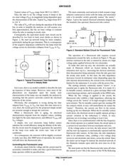
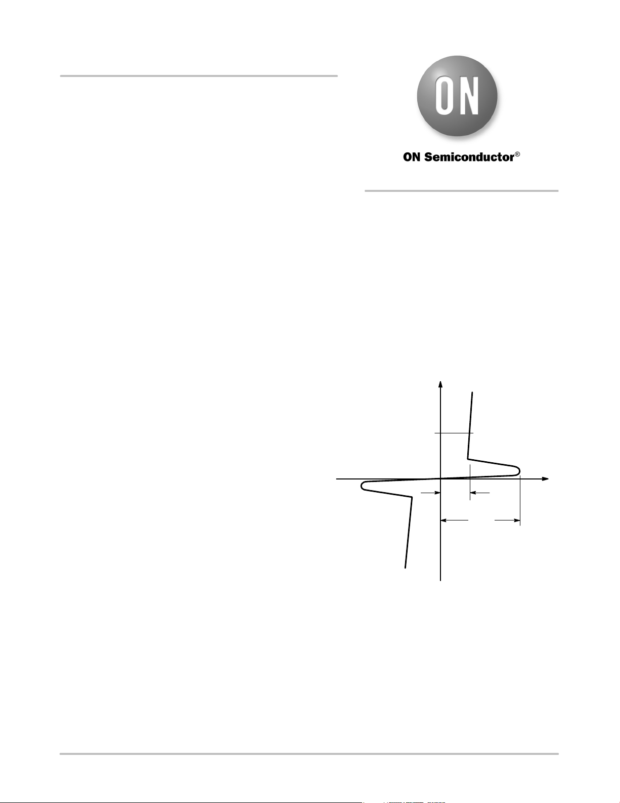
Fluorescent Lamp Operation
When the lamp is off, no current flows and the apparent
impedance is nearly infinite. When the voltage across the
electrodes reaches the V
trig
value, the gas mixture is highly
ionized and an arc is generated across the two terminals of
the lamp. This behavior is depicted by the typical operating
curve shown in Figure 1.
Figure 1. Typical Low Pressure Fluorescent
Tube I/V Characteristic
I
V
I
nom
V
on
V
strike
The value of V
strike
is a function of several parameters:
− gas filling mixture
− gas pressure and temperature
− tube length
− tube diameter
− kind of electrodes: cold or hot
APPLICATION NOTE
http://onsemi.com
Verzeichnis