
herunterladen
Application Specification
©2012 Tyco Electronics Corporation, a TE Connectivity Ltd. Company
All Rights Reserved
*Trademark
TE Connectivity, TE connectivity (logo), and TE (logo) are trademarks. Other logos, product and/or Company names may be trademarks of their respective owners.
1 of 12
TOOLING ASSISTANCE CENTER
1-800-722-1111
PRODUCT INFORMATION
1-800-522-6752
This controlled document is subject to change.
For latest revision and Regional Customer Service,
visit our website at www.te.com
LOC B
114-2153
Series 250 Positive Lock MK 1
Receptacle Connectors
27 AUG 12 Rev D
All numerical values are in metric units [with U.S. customary units in brackets]. Dimensions are in millimeters [and inches].
Unless otherwise specified, dimensions have a tolerance of ±0.13 [±.005] and angles have a tolerance of ±2°. Figures
and illustrations are for identification only and are not drawn to scale.
1. INTRODUCTION
This specification covers the requirements for the application of Series 250 Positive Lock MK I Receptacle
Connectors. These receptacle contacts are designed to accept a wire size range of 20 to 10 AWG.
One- and two position housings are available for your production requirements. The contacts are designed to be
mated with tabs containing holes for proper locking. These receptacle contacts are terminated by automatic or
semi-automatic machines.
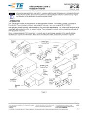
When corresponding with TE Connectivity Personnel, use the terminology provided in this specification to
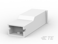
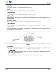
facilitate your inquiries for information. Basic terms and features of this product are provided in Figure 1.
Figure 1
NOTE
i
Release
Latch
Single Circuit
Housing (Typ)
Release
Latch
Retention
Nib
Receptacle
Contact
Insertion
End
Multiple Circuit
Housing (Typ)
One
Position
Flag
Housing
Wire
Barrel
Retention
Nib
Release
Latch
Mating End
of Housing
Series 250
Positive
Lock Flag
Contact
Series 250
Positive Lock
Contact
Secondary
Lock
Insulation
Barrel