
herunterladen
© 2008 Microchip Technology Inc. DS01213A-page 1
AN1213
INTRODUCTION
As embedded systems become smaller, a growing
need exists to minimize I/O pin usage for communica-
tion between devices. Microchip has addressed this
need by developing the UNI/O™ bus, a low-cost, easy-
to-implement solution requiring only a single I/O pin for
communication.
The standard configuration for a UNI/O bus combines
the serial clock, data, address, and control signals onto
the SCIO signal. This allows UNI/O devices to enhance
any application facing restrictions on available I/O
stemming from connectors, board space, or the master
device. But some applications can benefit from a
further reduction in connections.
This application note describes how a standard half-
wave rectifier and capacitor circuit can be added to
allow power to be extracted parasitically from the SCIO
signal. Guidance is offered for selecting the capacitor
value and diode based on application parameters such
as voltage and serial frequency. No modifications to the
standard UNI/O bus protocol are necessary. It is
assumed that the reader is already familiar with the
basic terms and operation of the UNI/O bus.
Within this application note, equations shown with a
heavy outline around them are critical equations used
to calculate an important parameter. The other equa-
tions are provided to show the steps necessary in
deriving the final equations.
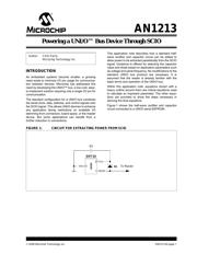
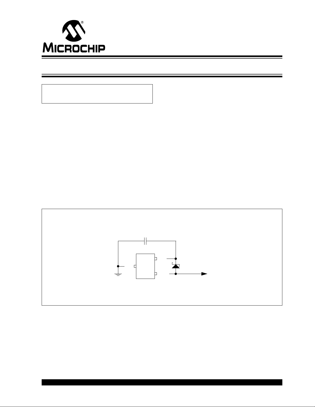
Figure 1 shows the half-wave rectifier and capacitor
circuit connected to a UNI/O serial EEPROM.
FIGURE 1: CIRCUIT FOR EXTRACTING POWER FROM SCIO
Author: Chris Parris
Microchip Technology Inc.
To Master
2
3
1
VCC
SCIO
V
SS
SOT-23
11XXX
D1
C1
Powering a UNI/O™ Bus Device Through SCIO